
Hopping Robot with Swing Leg
Published:
Investigated the effect of swing leg on hopping robot. 2.74 Bio-inspired robotics project.
Hey, what is this?
 Our inspiration came from single leg hopping. And we tried to gain some new insights from it. Here are the questions we wanted to answer through the project:
- What is the relative phase between swing and hopping legs that causes the robot to jump the farthest?
- What is the effect of active swing of the swing leg on robot average speed?
Intuitively, we argued that firing the swing leg forward would increase the ground reaction force and therefore leads to a longer hop. But how will the hopping distance vary with different firing time (we called it phase difference between two leg) and the firing time duration? Here comes our hypothesis:
- Active swing leg movement increase average speed of single-leg hopping.
- Phase difference between swing and hopping affect single-leg hopping speed.
- There exists an optimal phase difference between swing and hopping leg to maximize single-leg hopping speed.
Simulation

Deriving the system dynamic

We derived the dynamic using Lagrangian method with five generalized coordinates. To simplify the problem, we fixed the orientation of the hip (at point o). The motors for hip and knee are placed at O and A.
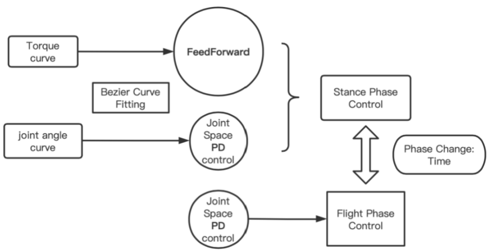
Control scheme overview
In order to control hopping leg behavior during experimental trials, control schemes were found separately for the two legs.
At first, we tried to optimize the whole process for hopping leg (hybrid dynamic with stance+flight). But then we realized it would be hard to find a feasible solution (contact is discrete!). So the hopping leg control was further separated into stance stage and flight stage control schemes to simplify optimization search space.
Stance phase
Optimization tool: CasADI, fmincon(fail)
Objective: maximize the speed before taking off
Decision variables: 4 Bezier control points for knee and hip motor, control time
Constraints:
- torque limits of the motors
- Body should not fall below the ground
- CoM should move forward
- Desired velocity angle
We first tried fmincon, but it failed to solve the problem. Then we tried to use CasADI which is an open-source tool for nonlinear optimization and used IPOPT to solve some feasible solution for stance phase. (thanks for Matt and Se Hwan).
Flight phase
- Hopping leg modelled using spring-loaded inverted pendulum (SLIP) model; defined by length from hip to foot and angle with the ground
- Joint-space PD control to track flight Bezier trajectory Parameterized by takeoff, landing, and two intermediate angles
Swing leg
- Joint-space PD control
- Two key parameters:
phase_shift: relative phase of leg swinging in relation to hopping leg
swing_ratio: duration of leg swing as a percentage of hopping leg stage duration - Actively hold position when not executing swing
- Define phase using beginning of stage
Continuous hopping
- Generate joint position trajectory. We first tried to repeat torque trajectory which failed to generate continuous hopping because it is sensitive to initial condition. So we only replicated joint position trajectory in the continuous hopping.
- Joint space PD control: use optimal joint position trajectory to control stance stage
Result


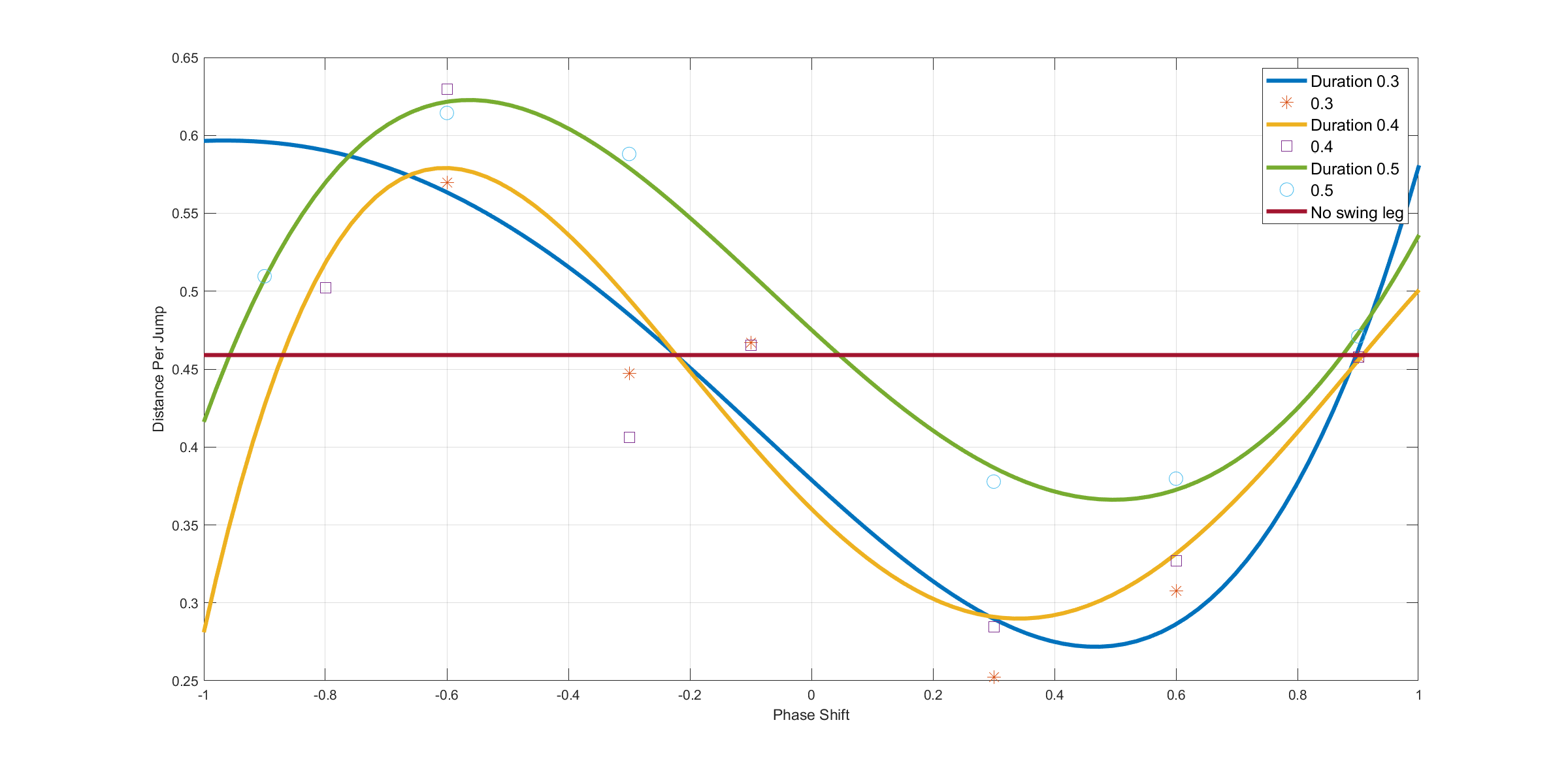
To look into the effect of two key varibles phase_shift and swing_ratio and sweep over the parameters space, we fixed swing_ratio to 0.3(blue) 0.4(yellow) and 0.5(green) to indicate the effect of phase shift. We used the longest jump joint position trajectory without swing leg as the baseline, which is shown in red.
Phase_shift: range [-1, 1], -1 means completely out phase when the swing leg goes the opposite direction contrast to hopping leg, while 1 means the the swing leg in phase with hopping leg.
phase_shift
Negative phase shifts seems to achieve longer hopping distances than positive ones. In the clear trends for the swing_ratio = .5 curve, the robot hops further when the swing leg leads the hopping leg (phase_shift < 0) than when the swing leg lags the hopping leg (phase_shift > 0). In fact, distance hopped is greater than the baseline control for the former and less than the baseline control for the latter. The curve of best fit hints strongly at a periodic, sinusoidal trend.
swing_ratio
A swing ratio of .5 was most successful for producing valid experimental runs. This is likely due to aggressive swings (swing_ratio = .3) perturbing the system beyond stable hopping behavior, and long swings (swing_ratio = .5) shifting the center of mass of the system for large amounts of time beyond what the hopping control can handle. As impulse is the integral of force over time, we hypothesize that there is a nontrivially optimal swing ratio for each phase shift value such that the system is stable and receives the largest impulse from the swing leg.
Hardware Experiment
Hardware setup
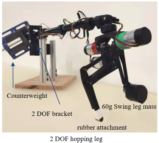
We designed a 3-DoF hopping leg with reference to the lab leg. We used three 12V brushed motor with 19:1 gearbox to drive swing leg and hopping leg. To see the effect of swing leg, we had to add some weight on it which made the robot harder to jump. To make it easier to jump, we used a boom limit its motion and add counter weight on the other end. The boom would influence the motion and change the rotation inertia of the system. But if we made the arm attached to the leg a lot longer than the arm attached to the counter weight, we can neglect the effect of the boom.
Control method
 For the stance phase control, we used feedforward torque (from simulation result) + PD control to follow optimized trajectories. For the flight phase control, we used PD control to restore to landing position. The control command frequency is 200hz while motor controller runs at 1000hz.
Hardware experiment
Future Work and Thoughts?
Generally, we were happy about what we achieved at the end. The simulation worked well and we collected some descent data to support our hypothesis. Also, the real robot hopped. During the exploration process, some problems remains:
- Limitation of off-line optimization: due to the fact that we only optimized for the stance phase, we had to control the flight phase and landing manually which is challenging and also no guarantee for optimal solution. In the future, we can modify the off-line optimization to online one, which will be in fact a MPC. And simplifying our optimization problem and doing linearization for dynamic can be essential.
- Contact dynamics is really challenging. There are two parts. First, even with ground truth in simulation, determining the flight time and lift off/landing time is a challenge and will influence the control scheme switch (I heard there are emerging methods to control flight and stance phases together but haven’t looked into it). The second is the contact model and how to handle the dynamic in the optimization. We used soft contact model which treats the ground as a spring and calculate ground reaction force (GRF) from the penetration. There were some undesirable behaviors in landing: the robot will slip for some distance or shake. I think, maybe a more realistic contact model, correct simulation frequency at contact and optimized control for contact can improve the performance.
- Sim-to-Real: transferring the result in simulation to hardware is also difficult. Our model in simulation is not the same in reality. So after transferring the position command into hardware, we didn’t get the robot worked and had to tune the controller again. The sim2real gap is a good reason why the accurate model and robust controller are important.
Acknowlegements
This project was done with Valerie Chen, Cunxi (Jimmy) Dai and Jesse George-Akpenyi. Thanks for the great support from Prof. Sangbae Kim, Se Hwan Jeon, Matthew Chignoli and other TAs.